Calculator – Wind/Sail — sheet load/travel
Calculator – Drum type — torque/travel
Calculator – Arm type — sheet load/travel
Calculator – Drum diameter — rotation/sheet travel
Calculating sheet load and travel for different sails and wind speeds
The load on the sail sheet is dependant on four factors:-
(a) the sail area
(b) wind speed (at the vertical C of E)
(c) the distance of the Centre of Effort to the point of sail rotation
(d) the distance of the sheet attachment point/clew to the point of sail rotation
Wind/Sail — sheet load/travel calculator
| 4 | Beaufort wind speed |
| 100 cm | C of E above WL |
| 5.27 m/s | Height corrected wind speed |
| 0.17 g/cm2 | Wind pressure on sail |
| 10560 cm2 | Sail area |
| 1.79 Kg | Load on sail through C of E |
| 52 cm | Distance from sail's Centre of Effort to luff |
| 100 cm | Distance from sheet attachment point to luff |
| 1.92 | Mechanical Advantage (Sheet/C of E distances from luff) |
| 0.93 Kg | Sheet Load (sail load / MA) |
| 1.32 Kg | Sheet Load with boom at 90 degs |
| 1 | Safety factor |
| 0.93 Kg | Safe Sheet Load |
| 1.32 Kg | Safe Sheet Load with boom at 90 degs |
| 100 cm | Distance from sheet attachment point to luff |
| cm | Distance of deck attachment point from luff |
| 100 cm | Sheet Travel with boom at 90 degs |
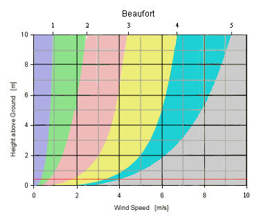
What is Wind Shear?
Wind speed increases with height from zero at surface level, its called "Vertical Wind Shear". The strength of wind speeds are specified at a standard height of 10m, the graph below shows approximately how the wind decreases below the standard height.
Calculate the wind speeds for different heights.
V = Vref x log(Z/Z0) / log(Zref/Z0)
V = wind speed at the C of E height Z
Vref = Standard reference speed at reference height Zref
Z0 = Standard roughness length of 0.0002m
Calculate the wind velocity pressure on the sail.
Vp = 0.00612V2 g/cm2
V = Wind Velocity in m/s measured at sail's C of E
Vp = Velocity Pressure in Pascals (Pa), Wind pressure on sail
Vp = 0.6V2 pascals
1N/m2 = 1Pa
1kg/m2 = 0.102 x N/m2
1g/cm2 = 0.1 kg/m2
Sheet Travel
The size of the sail governs the amount of sheet travel required to pull the sail from fully out to fully in.
The use of booms allows the location of the sheet attachment point to be altered independantly of the sail size, but they have limitations as they cannot be used for twin foresails, creat an overlapping sail or to be authentic.
The position of the centre of effort of the sail is fixed. The position of the sheet attachment point can be altered to decrease the load on the sheet. Mechanical Advantage is the distance between the sheet attachment point and its point of rotation ie forestay/gooseneck divided by the distance of the Sail's C of E from its point of rotation. If they are equal then the sheet load is the same as the load on the sail.
The aim is to get the sheet attachment point as far a way from its point of rotation as possible so reducing the sheet load. MA of 2 halves the sheet load.
As in all mechanics, you pay a price, As you decrease the sheet load you increase the length of the sheet travel. The result is a compromise dependant on other factors especially the servo .
Drum Sail Servo
The servo has two seperate functions to supply a force for the sail sheet and to control the amount of sheet travel. These functions could be in two stand alone units
The advantage of the arm type sail servo is that it is easy to increase the sheet travel by moving its attachment point on the arm. Moving it out increases the sheet travel but decreases its usable power, but this is not a problem if the servo has sufficient power.
The length of the arm is limited by the size of boat and this also restricts the length of sheet travel. The useful angle of rotation is limited as the more the arm rotates the less power is available , 0 at 90 degs (do you remember Vector Diagrams in Physics?)
The advantage of the drum type is that it gives an increased length of sheet travel dependent on the drum effective diameter and the number of rotations available.
Servo manufacturers and retailers could be breaking Trade Discriptions Act for example The Hitec HS-785HB spec says it gives 3 1/2 turns. When you open the box and read the instructions it's different. It says " The drum on this winch usually rotates between 2 and 4 turns depending on the model of transmitter used..... with a Hitec radio, it rotates 3 1/2 turns"
I am experimenting with an old Futuba Skysport 4/FPR115F. I get 4, 4 1/8, 3 1/8, 4 1/8 turns on the 4 channels. If I now build my boat using this servo, how can I know if it will work the same with another R/C set up?
Hitec says in their instruction leaflef "With an effective radius of 19mm the force available exceeds 5.67kg which is sufficient to control a sail area of 6450cm2"
This is nonsense. What about Mechanical advantage due to the positioning of the sheet attachment point?
Hitec goes on to say "Do not attempt to reduce the sheeting times by increasing the drum diameter or by moving the sheet attachment closer to the gooseneck and reducing the number of turns. This will reduce the battery life and could damage the winch".
If you stay under the Torque rating for the servo, this is surley nonsense? Obviously, if you increase the load you will decrease the battery life. How can it damage the servo? Is their product not fit for purpose?
"Adjust the throw of the transmitter stick (or ATV) to make the sail drum rotate the required number of turns". If you can only use 2 turns out of a possible 4, you will reduce the controllability of the sail as you will only be able to use half the stick travel. Surley you want to use maximun stick throw = drum rotation changing the sheet travel length by altering the drum diameter? Halve the number of turns, halves the amount of sheet travel which then doubles the amount of torque required.
Servo Drum diameter/torque
Servo Drum diameter
Calculate the drum diameter knowing the servo torque and sheet load.
Drum rotation and Torque calculator
Calculate the number of drum rotations and the servo torque.
| 19.8 cm | Sheet travel |
| 39 mm | Drum diameter + cord thickness |
| 3.07 kg | Sheet load |
| 12.3 cm | Drum circumference |
| 1.6 | Number of turns |
| 12.0 kg.cm | Servo torque required |
Drum type servo comparision chart
| Make | Model | £ | Turns | cm/rev | kg.cm@V | Gears | Nload/Stall |
|---|---|---|---|---|---|---|---|
| RMC | 208DL | 130 | 7.2 | 6/8/10/13 | 14@7.2 | Plastic | .45/6A |
| RMC | 308D | 135 | 6.0 | 6/8/10/13 | 21@7.2 | Metal | .85/16A |
| RMC | 308HD | 135 | 6.0 | 6/8/10/13 | 21@7.2 | Metal | .85/16A |
| Futuba | S5801 | 110 | 6.0 adj | 13.2 3 | 9.8@7.2 | Metal | ?/1.6A |
| Graupner | 5173 | 105 | 5.5 adj | 12.0 | 10@7.2 | Metal | .31/1.2A |
| Graupner | Eco | 76 | 5.5 adj | 7.9 | 4@7.2 | Plastic | ? |
| Robbe | F8336 | 80 | 5.0 1 | 5.6/12/19 | 8@6 | Plastic | .23/1.4A |
| RMC | 208D | 130 | 4.8 | 6/8/10/13 | 11.2@7.2 | Plastic | .45/6A |
| Hitec | HS-785HB | 21 | 4.0 2 | 12.0 | 13.2@6 | Karbonite | .25/1.8A |
| GWS | S125 1T | 14 | 1.0 | 13.0 | 6.6@4.8 | Plastic | ? |
| GWS | S125 1/2T | 14 | 0.5 | 6.5 | 6.6@4.8 | Plastic | ? |
| 1. 4 turns with Futaba r/c kit. 2. 3.5 turns with Hitec kit, 4 with digital. 3. Could be 11 or 9.5 cm/rev. | |||||||
| Make | Model | Angle | Neutral usec | Travel usec | Deadband usec | Modifiable |
|---|---|---|---|---|---|---|
| RMC | 208DL | 1500 | ||||
| RMC | 308D | |||||
| RMC | 308HD | |||||
| Futaba | s5801 | 180 | 1500 | No | ||
| Graupner | 5173 | |||||
| Graupner | Ec0 | |||||
| Robbe | F8336 | |||||
| RMC | 208D | |||||
| Hitec | HS-785HB | 3.5 Turns | 1500 | 1100 – 1900 | 5 | No |
| GWS | S125 1T | |||||
| GWS | S125 1/2T |
Arm Sail Servo Mechanisms
My first instincts when looking at existing layouts on how to control sail movement was one of scepticism. Any lever mechanism is inherently a poor transmitter of power and there were obvious problems with friction.
Drum sail servos were the obvious answer as they give constant sheet force but as explained before, it is impossible to know how exactly many rotations they will give as it varies for different manufacturers and different Tx/Rx set-ups.
So it was back to basic principles.
The Sail Arm is a simple mechanism converting a rotary force (and motion) into a linear force (and motion). It consists of a fixed length rotating arm with the sheet cord sliding through a fixed point (pulley, eye or deck tube).
The mechanism only works thought 180 degrees when the cord is under tension.
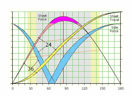
I wanted to find out what factors effected Sheet Travel and Sheet Force. Initially, I drew the mechanisms to scale, but this was too slow, so I wrote a small programme in PHP to simulate drawing using basic trigonometry. (sin, cos, tan). (see below)
I originally thought that the maximum force was exerted when the servo arm was at 90 degrees. This is not only false but there is a range of arm angles where the mechanism actually multiplies the torque. The purple section below is an example.
The servo torque force on the servo arm is always at 90 degrees to the arm at the point of sheet attachment.
All angles are calculated from a line between the servo shaft and the first fixed point through which the sheet passes (called the Fixed Point).
The distance between the servo shaft and the Fixed Point is critical as it is used in all calculations.
There is no sideways force on the servo when the sheet is at right angles to the arm. This is when the lines of action of the torque and sheet force are in a straight line.
The calculations used for the chart below, used a standard 12cm sail arm and a nominal 10kg.cm servo torque.
24 and 36cm were used for the distances between the Servo to Fixed Point.
Factors to establish.
1). Most efficient distance of the fixed point from the servo centre.
2). Arm angle giving the maximum sheet force.
3). Range of arm angles giving usable sheet force.
4). Range of usable sheet travel.
5). Forces on servo mountings.
6). What is the correct angle for the sheet leaving the fixed point.
1). Most efficient distance of the fixed point from the servo centre.
Increasing the fixed point over 36cm from the servo centre made little difference. Most variations happened below 24cm.
The calculator will not work if the distance is not bigger than the arm length.
2). Arm angle giving the maximum sheet force.
The angle of maximum torque is dependant on the arm length and the servo/fixed point distance. For 13cm with 12cm arm this is at 58 deg. For 36cm, it is at 95 deg.
I was not expecting this, but it’s caused by this type of mechanism.
3). Range of arm angles giving usable sheet force.
Looking at the chart theoretically, it would seem that there is little point in using servos that give over 90 deg of rotation. The grey area on the chart shows 90 deg range and the yellow shows 120 deg. The power loss is great at the extremes.
However, when searching the Net I came across the R/C Sail Forum. The following are edited extracts from one post.
"Most sail servos are mounted with the arm pointing across the boat (90 deg). The sheet is pulled tight at this point (90 deg) and let out when aft (180 deg). This means the adjustment is coarsest when the sheet is pulled in (90 deg) going to windward and finest when out (180 deg) on the run. This is the reverse of what is needed. To reverse this, put the arm forward (0 deg) when close hauled and at 90 deg when on the run." (The post make no mention that this is also around the point of maximum servo torque and the multiplier effect).
"If the arm is orientated to go "just" pass 0 deg, the sheet will be locked in place with the sheet pulling against the servo stop thus using no power when fully sheeted in"
This highlights a problem using servos. "Hunting" This is when the servo is continually making small correcting movements caused by the sheet load fluctuating under constantly varying wind pressure. (Hunting to find the correct position). I would assume that servos used in helicopters and aircraft have to be very sensitive whereas in boats this will cause continual hunting resulting in a rapid loss of battery power.
"I would think that with the minimum load imparted by a "Footy’s rig, that any alignment would do." Footy's are one foot long! Will this arrangement work in bigger boats? The only way is to try it out.
The post goes go on to explain other useful applications of lever mechanisms where you can set–up differential movements between the boom and jib using only one servo. My intention is to have one servo for each sail of the four sails on the 1/10 scale Jolie Brise plus rudder and motor.
4). Range of usable sheet travel.
Unless you are using the very extreme ends of arm rotation (30 deg), the sheet travel is proportional to the angle of rotation.
5). Forces on servo mountings.
Every layout I have seen shows the servo mounted inline with the boat’s centerline. This is wrong. It should be mounted in relation to the line between the servo shaft and the Fixed Point. Servos should also be given additional lateral support as the two small fixings are so close together they act as a single fixing (pivot).
The calculator shows that there is a particular angle where there is no side load on the servo. This is the best angle to minimise forces. It is not at the point of maximum sheet force.
As a product designer, the more I look at R/C equipment, the more disappointed I become.
Servo bodies should be square as the linear forces acting on them are not in one direction but rotate. They are designed around the requirement of aircraft models.
I have never seen a servo tilted so that the sheet is aligned with the arm so eliminating arm bending on the thin section. The solution is so simple, add a thin web to create a tee section, it will cost the manufactures little. Nobody needs to use aluminium arms if the plastic ones are designed correctly.
6). What is the correct angle for the sheet leaving the fixed point?
As the arm rotates, the sheet angles increases to a maximum then decreases. To find the central point of sheet angular movement, calculate the minimum and maximum angles and then the mid point. This is not the same as the angle of maximum sheet force.
If the Fixed Point is the deck tube, the sheet has to make a right angle resulting in power lost due to this angular change and to friction. It would make sense to have the servo below deck and the arm above.
If the arm is below deck then some form of puller/roller system should be used to change sheet direction, making allowances for the varying sheet angles. If positioned correctly, this will also stop the servo arm bending.
Arm Sail Servo Calculator
Arm type — sheet travel/load calculator
| 10 kg.cm | Servo torque |
| 13 cm | Distance between servo centre and sheet fixed point |
| 12 cm | Arm length |
| 70 deg | A – Arm angle |
| 67 deg | S – Fixed servo angle to centreline with no servo side force |
| 52 deg | B – Sheet to centreline angle |
| 58 deg | C – Sheet to arm angle |
| 13.4 cm | Sheet travel |
| 15.2 kg | Sheet force |
Arm type servo comparision chart
| Make | Model | £ | Angle | Arm cm | kg.cm @ V | Gears | Nload/ Stall |
|---|---|---|---|---|---|---|---|
| Hitec | HS-7950TG | New | 25/29 @ 6/7.4v | Titanium | |||
| Futuba | S3306 | 35 | 90 | 20/24 @ 4.8/6v | Nylon | ||
| Hitec | HS-815BB | 29 | 140 | 10.8 | 20/25 @ 4.8/6v | Plastic | 0.1/0.7A |
| Futuba | S5301 | 78 | 90 | 17/21 @ 4.8/6v | Metal | ||
| Hitec | HS-755MG | 26 | 80 | 10.8 | 12/14 @ 4.8/6v | 3 x Metal | 0.25/1.8A |
| Hitec | HS-765HB | 25 | 140 | 10.8 | 12/15 @ 4.8/6v | Karbonite | 0.25/1.8A |
| Futuba | S3801 | 45 | 125 | 12.0 | 11/14 @ 4.8/6v | Metal output | |
| Hitec | HS-755HB | 22 | 80 | 10.8 | 11/13 @ 4.8/6v | Karbonite | 0.25/1.8A |
| Futuba | S3802 | 45 | 140 | 12.5 | 9/11 @ 4.8/6v | Metal output | |
| Futaba | S3003 | 9 | 90 | – | 3/4 @ 4.8/6v | Nylon | 0.7/?A |
| Hitec | HS-322HD | 7 | 80 | – | 3/4 @ 4.8/6v | Nylon | 0.2/0.8A |
| Make | Model | Angle | Neutral usec | Travel usec | Deadband usec | Modifiable |
|---|---|---|---|---|---|---|
| Hitec | HS-7950TG | 90 | 1500 | 1100-1900 | 2 | Digital |
| Futaba | S3306 | 90? | 1520 | 1120-1900 | ? | |
| Hitec | HS-815BB | 140 | 1500 | 1100-1900 | 8 | No |
| Futaba | S5301 | 90 | 1520 | 1120-1900 | No | |
| Hitec | HS-755MG | 80 | 1500 | 1100-1900 | 5 | No |
| Hitec | HS-765HB | 140 | 1500 | 1100-1900 | 5 | No |
| Futaba | S3801 | 125 | 1520 | 1120-1900 | No | |
| Hitec | HS-755HB | 80 | 1500 | 1100-1900 | 5 | No |
| Futaba | S3802 | 140 | 1520 | 1120-1900 | No | |
| Futaba | S3003 | 90 ? | 1520 | 1120-1900 | Y ? – ? |
|
| Hitec | HS-322HD | 80 | 1500 | 1100-1900 | 5 | n |
What is a servo
“A servomechanism, or servo is an automatic device which uses error-sensing feedback to correct the performance of a mechanism. The term correctly applies only to systems where the feedback or error-correction signals help control mechanical position or other parameters. For example an automotive power window control is not a servomechanism, as there is no automatic feedback which controls position–the operator does this by observation. By contrast the car's cruise control uses closed loop feedback, which classifies it as a servomechanism.
Typical servos give a rotary (angular) output. Linear types are common as well, using a screw thread or a linear motor to give linear motion.
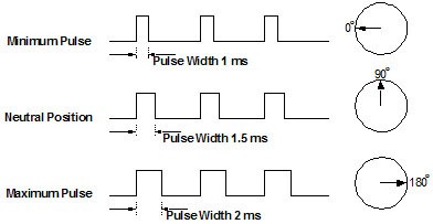
RC servos are composed of a DC motor mechanically linked to a potentiometer. Pulse-width modulation (PWM) signals sent to the servo are translated into position commands by electronics inside the servo. When the servo is commanded to rotate, the DC motor is powered until the potentiometer reaches the value corresponding to the commanded position.
The servo is controlled by three wires: ground (usually black/orange), power (red) and control (brown/other colour). ... The servo will move based on the pulses sent over the control wire, which set the angle of the actuator arm. The servo expects a pulse every 20 ms in order to gain correct information about the angle. The width of the servo pulse dictates the range of the servo's angular motion.”
From Wikipedia
From the Society of Robots
Signal Wire (Yellow/Orange/White wire). While the black and red wires provide power to the motor, the signal wire is what you use to command the servo. The general concept is to simply send an ordinary logic square wave to your servo at a specific wave length, and your servo goes to a particular angle (or velocity if your servo is modified). The wavelength directly maps to servo angle.
The standard time vs. angle is represented in this chart:
For more details go to Servo tutorial from the Society of Robots.
1.5ms is the null point at the central point of a stick or slider travel on the Tx.
All sliders and joy sticks must be centred before switching on. If a joy stick or slider is at an end point, the servo will crash against its internal stops when the Tx is turned on, this might strip the gears.
What is a servo. A different answer.
DIY Servo Driver
Make your own Servo Driver to test your servos without having to use your Tx/Rx. Only Servos.
Servo Driver Tests - Pulse Width
Arm Servos
Two servo testers were made and used to test a variety of arm and drum servos.
Each servo was rotated over its full range to find the angle of rotation.
Tester 2 covers the pulse width range 0 to 2.4mS and was able to rotate the servos over their full travel.
Tester 1 covers the pulse width range 1 to 2mS similar to Tx/Rx systems and shows the limited servo rotation.
The results were compared with the full stick travel of two Tx/Rx systems.
Drum Servos
GWS 125 1T is sold as 1 Turn but only turns 290 degres when using a Tx/Rx and 2 1/4 turns with Tester 2.
Hitec HS 785-HB is sold as 3 1/2 turns but 3 3/4 turns when using Tx/Rx. Amazingly, it will actually turn 9 times.
Both drum servos will continuously rotate at the limits of the pulse range.
The tests show that the servo testers were accurate. The charts show inconsistances between servos, Tx/Rx are not using the servos to their maximum potential and manufacturer's data is incorrect.
Servo Hunting and Chattering
The Tx sends out a control signal to the servo’s microprocessor. The servo’s Pot (potentiometer/variable resistor) sends out a reference signal. When the two match, the servo does nothing
In a sailing boat, the servo arm/drum/pot constantly moves backwards and forewards due to the varying wind pressure and wave motion. The microprocessor senses this and making the servo motor osscillate trying to correct itself. This is called Hunting and the noise of the motor and gears is called Chattering
Servo Deadband
The deadband is the small difference between the control and servo reference signals when the servo motor is stationary. They can never be exactly equal.
Analogue servos are made with a deadband of about 5usec.
So if the difference between the two signals is smaller than the servo’s deadband, the servo does not move. If it is larger, the motor moves until the sigal difference is lower than the deadband.
For sail boats, the larger the deadband, the less sensitive it becomes to sail pressure fluctuations.
Hitec HB815BB has a 8usec deadband. Digital servos have no deadband! read Futaba's article Digital FET servos
Servo Links
Radio controlled models – Wikipedia