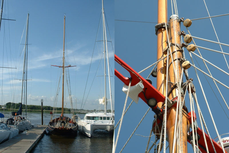
Jolie Brise was taken out of the water in the winter 2009/10 as it was damaged after being hit by a 80ft yacht in a race. I took the opertunity to measure and photgraph all the parts and then produce drawings to 1:10 scale for accuracy. The mast and spars took two x 2m drawings and the fittings 15 x A3 drawings.
Spars
The Spars were made up from 4 square pieces with the grain direction rotated so as not to be parallel. This gives the max bending strength.
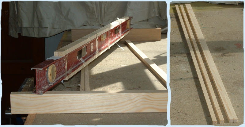
My local timber yard cut them +5mm from standard softwood (Pine type) choosen for close grain and free from knots. (Main mast is 1.6m).
Two pieces were glued together on a straight surface. I used a sprit level, so both directions were straight, tape held them down and squeed out the glue.
Some of the sides were not planned exactly square so I glued them in pairs then planned/sanded the mating surfaces flat before gluing.
To make the Spars round, I first marked out two lines on one pair of opposite sides giving the diameter including any taper. They were the rough cut on a band saw then accurately planned down to size.
This was repeated for the other pair of sides resulting in a square/rectangle to the overall dimensions.
After making the second spar I found it quicker to be very accurate at every stage.
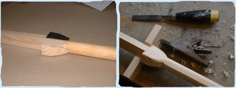
The next stage was to mark out parallel lines down the length of all sides to give an octagon. Two block were cut at 45deg to hold the spar when it is being planned.
Watch the grain directions as they may be opposite also take care that all the flats are the same dimensions allowing for taper.
This was repeated to give 16 sides and then again for 32 sides. The main Mast is 28mm diameter. The Spars were rounded using glass paper, not as accurate as turning,
but difficult to see the inaccuracies. The boom's centre is deeper than the ends but straight on the top.
The metal rectangle is a scraper often used for removing varnish/french polish. The Jack Plane is more accurate and much lighter for this kind of work.
Bowsprit
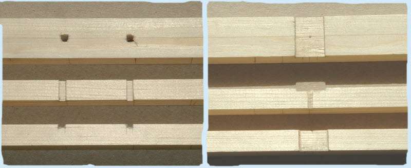
Trying to a drill hole and slot on the centreline will be a problem as the drill will hit the hard glue line and bend away. The spar was made in two halves with the slot and pulley shaft hole cut into both pieces. This was then glued together.
It was then shaped to the dimensions and coated with varnish.
The bowsprit is supported at the bow with a metal ring and the outer end of the bowsprit has to be positioned on the boat's centreline. To set the correct distance of the bowsprit to the bow, a cord was attached to the centre of the transom and to a cupboard with the cord passing over the centre of the bow stem.
A mahogany block was drilled with a 22mm hole and cut one side 15mm from the centreline, this was then fitted onto the bowsprit. The bowsprit square end was then rested on the winch and the block on the bow stem. The block was cut back until the bowsprit outer end was on the centre line.

The bulwark was taped and vertical lines drawn to represent the edges of the bowsprit. A horizontal line was drawn halfway between the rail and the red line. An ellipse was drawn and the bulwark cut. It was a case of trial and error to get the size right.

